The urge is to make this write-up a typical "journey through the process", almost a step-by-step to RE this particular thing - but I think that betrays the true nature of reverse engineering. Besides, I've done that before.
There's nothing linear about this: new discoveries clarify previous assumptions, ideas you carelessly throw around or stumble upon become crucial to progress, and by gosh do you make a ton of mistakes.
Let's just talk about some interesting things instead.
Reverse engineering has a strong reliance on breadth of knowledge. Plenty of "a-ha!" moments are when two concepts collide; when what you're seeing in a messy disassembly or a block of opaque hex suddenly looks familiar and the dominoes begin to topple. The hope is that this expands your breadth of knowledge, if only by just a bit, to create the familiarity that knocks over that first domino.
File systems, and flash file systems
Most storage media is divided into blocks on which basic read/write/erase operations are performed. Interacting with the media is at this block level - writing an individual byte means reading the entire block into memory, changing the byte of interest, then writing the modified block in its entirety back to the media. Flash media takes these block-level operations to another level, only guaranteeing you'll get anywhere from 1,000 to 1,000,000 erase/write operations per block before the block begins to fail and the data you read might no longer match the data you wrote.
So, we'd like to store some files. Maybe we'll choose to take each file, write its filename and contents to the media, and then write the next file straight after it - blocks be damned. We'll add some length bytes to indicate how long the filename is and how many bytes the file's contents are, and pretend our media is simply a contiguous, byte-addressable memory. Problem solved, right? We've got a file system now, yeah?
Maybe one of your files is a log, and you'd like to add a new message to the end. We've reached a snag - the next file starts on the byte immediately after the last byte of the file we're updating, so there's no room to just write another byte and increment the length. We could read every file after the one we're updating into memory, writing their filenames and data back to our storage media offset by one byte, then append our new data and update the file's length. Now every time you modify a file you need to rewrite tens, maybe hundreds or thousands of blocks - enjoy the delay if your file is near the start of the media, and watch your flash memory fail much quicker than you'd like.
Cluster chains
Instead of ignoring the blocky nature of our storage medium, let's embrace it. Rather than mandating that our files occupy a contiguous portion of our media, we'll form a chain of blocks which when read in the correct order, yield the contents of our file. Each block is either the end of the chain, or tells us which block contains the data which comes next.
Updating a file becomes much easier now - find the last block of the file data, and check if it has any free space. If it does, we can write our new data to the last block and update the file's length, completing our operation. If the last block is full, or the amount of data we need to write is larger than the free space in the last block, we can add another block onto the chain to continue the file. Since each block points us to the next block in the chain, there's no need for adjacent data in the file to be stored in adjacent blocks. We're free to find an unused block anywhere and write our excess data to it.
There's no one way to keep track of our chains. The FAT file system dedicates one or more blocks to the job (the cluster map), treating them as an array where next_block = cluster_map[current_block]. A value of next_block is dedicated to marking that the current block is the end of the chain. This approach isn't great for flash memory though, since every time we need to modify a chain we'd need to read/update/erase/write the cluster map, wearing one of the most important blocks in our file system out extremely quickly.
The RN-171's "tag flash file system"
Some of the firmware files distributed for the RN-171 are in a mif format, containing several individual files (HTML documents, PNG images and executable code) which end up on the device. The contents of these mif files are written directly into the module's external flash memory and thus contain a small file system suited to flash memory.
Chains
When we take a look at the first bytes of each 4 KiB (= 0x1000 byte) flash block, a curious pattern emerges.
00000000: 00ff ffff 0301 ef02 045a 1e65 f101 0c64  .........Z.e...d
00001000: 01ff ffff 0301 ef02 045a 1e65 f101 076e  .........Z.e...n
00002000: 0203 ffff 0301 fcba 0440 00cc 80b5 0440  .........@.....@
00003000: 02fe ffff f090 1020 0070 002f 0ea2 16e0  ....... .p./....
00004000: 0405 ffff 0301 fcba 0440 00cc 20b5 0440  .........@.. ..@
00005000: 04ec ffff 0010 8600 e985 0052 8500 5550  ...........R..UP
00006000: 04ff ffff 2564 0d0a 4176 6572 6167 653d  ....%d..Average=
00007000: 0708 ffff 0301 fcba 0440 00d0 90b5 0440  .........@.....@
00008000: 07db ffff 5f45 6e72 6f6c 6c65 6542 7569  ...._EnrolleeBui
00009000: 090a ffff 0301 fcba 0440 0066 f0b5 0440  .........@.f...@
0000a000: 09d1 ffff 2845 4150 2069 6420 2564 2920  ....(EAP id %d)
0000b000: 0b0c ffff 0301 fcba 0440 0098 30b5 0440  .........@..0..@
0000c000: 0bc2 ffff f082 1040 0cc2 2340 0070 0097  .......@..#@.p..
0000d000: 0dff ffff 0301 fcba 0440 01f0 40b5 0440  .........@..@..@
0000e000: 0e0f ffff 0301 fcba 0440 01eb 30b5 0440  .........@..0..@
0000f000: 0eff ffff c204 a3e4 c200 4000 1080 0096  ..........@.....
00010000: 10ff ffff 0301 fcba 0440 01f3 20b5 0440  .........@.. ..@
# some bytes removed #
00023000: ffff ffff ffff ffff ffff ffff ffff ffff  ................
00024000: ffff ffff ffff ffff ffff ffff ffff ffff  ................
00025000: ffff ffff ffff ffff ffff ffff ffff ffff  ................
00026000: ffff ffff ffff ffff ffff ffff ffff ffff  ................
Several blocks begin with their own address shifted right by 12 (i.e. divided by 0x1000) and the second byte of many blocks has a value not far off the first. Sometimes the first byte is 0xff, sometimes the second byte is 0xff, but the second byte is always 0xff if the first byte is 0xff.
This is the file system's chain tracking mechanism. Each block begins with two bytes indicating both the block where the chain starts, and the next block in the chain. If the block isn't part of a chain and is unused, the first byte is 0xff, and if the block is the end of a chain, the second byte is 0xff.

Placing the chain data within each block is a much more flash-friendly approach than dedicating a block as FAT would. Adding another block to the chain requires rewriting only the last block of the file, to update the next block index, and deleting a file can be accomplished by erasing the page as it sets the start block index to 0xff. As such, the wear we put on the flash will be distributed around, rather than placed on a single block.
To dump the file system contents, we can iterate through every block, identifying those that start a chain when their first byte matches the block's index (the address shifted right 12). We can then walk the chain using the next block index in each block's chain header to rip out the full file contents.
Tags
With the data from a bunch of chains in hand, we'll turn to deciphering how each file is structured. Some begin with some bytes and the filename, whereas others have their filename at the end of their data, in the last block of their chain.
# file beginning at block 00
00000000: 0301 ef02 045a 1e65 f101 0c64 756d 6d79  .....Z.e...dummy
00000010: 6361 6c2e 6461 74ff ffff ffff ffff ffff  cal.dat.........

# file beginning at block 0d
00000000: 0301 fcba 0440 01f0 40b5 0440 01f0 40bc  .....@..@..@..@.
00000010: 0413 5ba7 88b1 9c3e 0310 0000 c028 600c  ..[....>.....(`.
# some bytes removed #
00000fb0: 4001 f098 4001 f0a0 0204 5a1e 65f1 0115  @...@.....Z.e...
00000fc0: 6765 745f 6c69 622d 455a 582d 3438 332d  get_lib-EZX-483-
00000fd0: 7232 3134 311f 0101 ffff ffff ffff ffff  r2141...........
That discovery throws "fixed length header per-file" out the window. Instead, this file system takes a more abstract view of files as a collection of "tags", each with a type/identifier and some variable-length associated data. One tag stores the filename, another a bit mask of flags, and another the actual file contents.
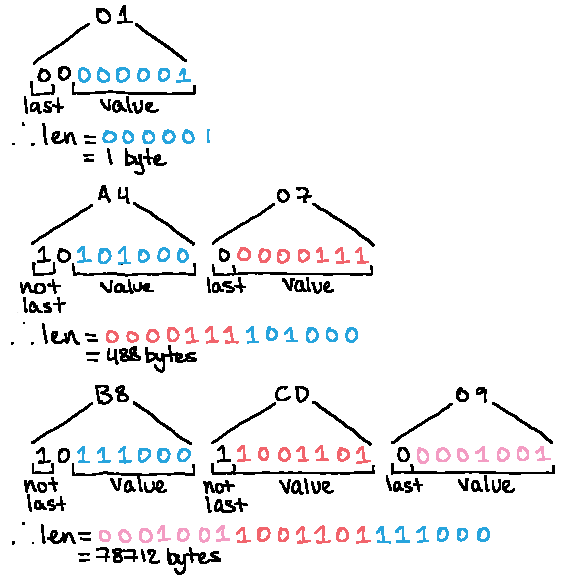
We can now step through the file tags manually. File 00 begins with an 03 01, a tag type 0x03 with length 0x01, which gives it the value 0xef. Once we make our way to the filename, we see a tag beginning 01 0c: tag type 0x01, length 0x0c, which is exactly how long the string dummycal.dat that follows is. Problem: what happens when a tag has more than 0xff bytes of data?
A smart scheme's in play here. The quickest way to solve the problem of a field too narrow for the data it needs to store is to widen the field, but that's wasteful for the small tags which do have less than 0xff bytes of data associated with them. Instead, the tag length field is itself variable-length, storing only 7 bits of length data in each byte and using the 7th (top) bit to indicate if another length byte follows. In reality, the first length byte only stores 6 bits, as the 6th bit is dedicated to something I have no idea about, but the 7th bit still indicates if another length byte follows.
Each subsequent byte's value is prepended to the binary string, meaning adding extra length bytes can only increase the value.
Now we're in a position to interpret the tags associated with each file to extract them in a more friendly way.
Binaries
Several of the files on the device are binaries - either applications that can be run, or libraries that are (assumedly) dynamically loaded by applications. Being split over several blocks of the flash, they're most likely loaded into RAM and executed there, rather than executed in-place (XIP). Inspecting the tags of the executable files shows two with promising address-like values: 0xb5 and 0xba. Some experience suggests that one of these is likely to be a load address (where the binary should be copied into RAM) and the other the entry point (the address of the function to call to "start" the application), and determining which is which involves disassembling the binary assuming one address, and seeing how many cross-references in the assembly match up. When they all do, you've probably found the load address.
One trap in doing this is accidentally relying on relative data references, where the address of the data being accessed is specified relative to the instruction pointer. No matter the offset a binary is loaded to (in most cases) IP-relative references will always line up given a contiguous image, since +10 bytes is always +10 bytes, no matter where the image is in memory. Most of the time, jumps and calls are IP relative, so they're not great to rely on. Only absolute data references can help determine if your binary has been given the correct load address.
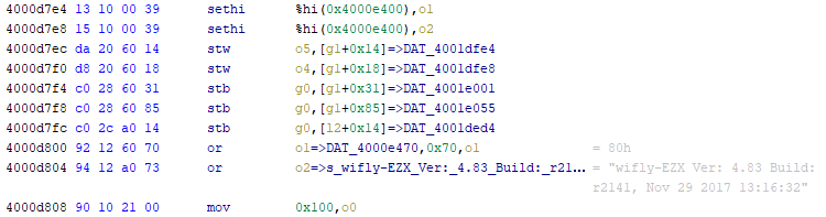
On SPARC, absolute references are often pairs of sethi %hi(address_hi), reg and or reg, address_lo, reg instructions, which together load the full address into a register.
Loading these binaries into a disassembler is now a matter of entering the right load address and poking around near the entry point for some valid assembly. In my extraction script, I took this a step further and dumped the binaries as ELF files - adding the machine code as a section located at the load address, and setting the entry point to the entry point from the 0xb5 tag. Though I didn't end up using any of these ELF files in the process, I think in future it's a good idea to keep in mind, especially if I had further RE work to do on the applications.
Bootloader
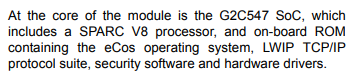
Debug interfaces are often horrible: "undocumented" as the norm, "badly documented" as a reason to celebrate, and "well documented" an absolute sight to behold. Since we've no documentation whatsoever for the G2 Microsystems G2C543 microcontroller on the module, we're mostly in the dark, though the flashing tool is publicly available.
$ ./flash_load.exe
flash_load
G2C547 Flash Loader Tool
Usage: flash_load [-h] [-d <dsu uart>] [-i <flash-image-file>] [-f] [-u] [-c] [-v]
    -h Display help.
    -d Serial port connected to the G2C547 DCOM flash loader port. Default: /dev/g2isp_dsu
    -i 'flash.bin' image flle name to be loaded (mandatory).
    -f Enable fast dcom load interface.
    -u Use ISP Force awake and reset functionality when loading the device.
    -c Disable check for the calibration sector.
    -v Enable verbose debug output.
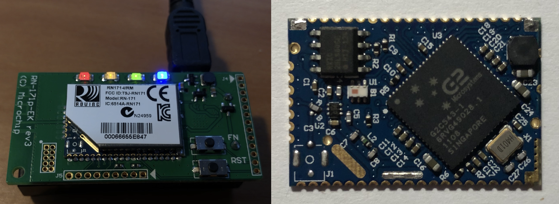
References to a serial port are promising, since it increases the likelihood the debug adapter G2/Roving/Microchip would try and sell you is no more than a UART and some GPIO pins for forcing the device awake and resetting it. We're still limited by the fact the debug UART (separate from the UART the dev board exposes on the USB connector) is only broken out in a 0.2 mm pitch header (the left most on the dev board pictured above), but some magnet wire, a 0.1" header, and a 3V3 USB UART solves that.
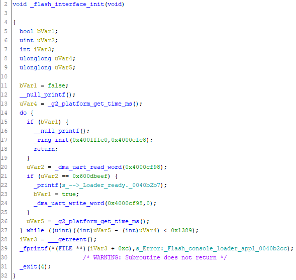
Delving into the binary gives promising signs along with plenty of debug symbols left over.
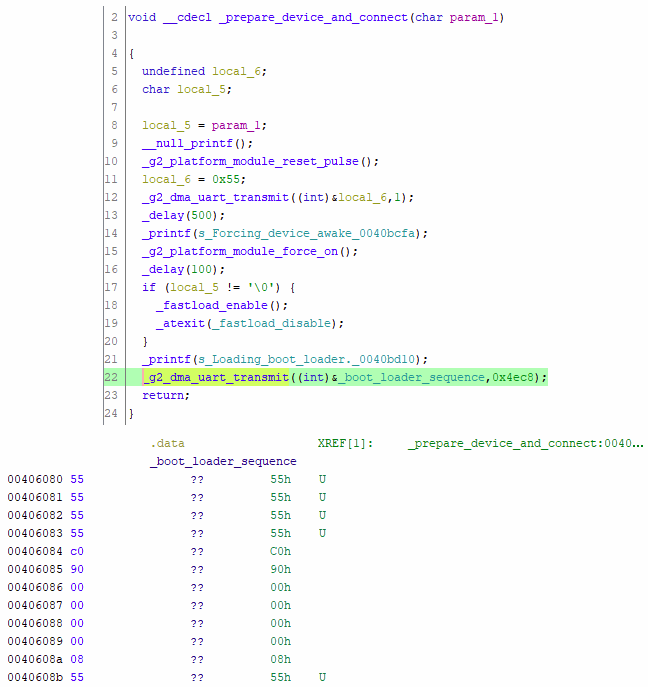
As it turns out, this 0x4ec8 byte long payload sent to the device is simply machine code with some framing to wake the chip up, tell it where in RAM to write the code, and how long the code is. This isn't an uncommon technique for devices to allow in-circuit programming, as it allows the method of programming to be changed after the device is taped out or almost completely overhauled. It can also allow for non-programming behaviour such as reading out the contents of an EEPROM without having to build the feature into the base firmware - just by modifying the payload which is sent to the device to do the job.
In this case, the firmware sent to the device implements an interface which allows the SPI flash to be read from and written to, but most importantly, allows arbitrary reads and writes to memory!
Capturing some serial traffic reveals the protocol.
# read from 0x4000cf98
WRITE   80 40 00 cf 98  .@...
READ    00 00 00 00     ....
# write to 0x4000cf98
WRITE   c0 40 00 cf 98  .@...
WRITE   00 00 00 00     ....
Some more investigation in the flash loader shows the low 6 bits of the first byte indicate the desired length of the transfer (in words), less 1, giving a maximum read size of 64 words or 256 bytes per read/write operation.
I decided here to write a small shell to push the blob to the device then give an interface to issue arbitrary reads and writes. This ended up being quite useful later on when figuring out which hardware registers corresponded to the GPIO ports on the device, since it was trivial to write to suspect registers and observe the effect.
$ # 800000a0 - direction, 800000ac - input, 800000b0 - output
$ python bootloader_shell.py bootloader_sequence.bin /dev/ttyS3
sending wakeup
sending bootloader payload
> w 800000a0 f0
wrote 800000a0 = 000000f0
> w 800000b0 f0
wrote 800000b0 = 000000f0
> r 800000ac
address 800000ac = 00 00 18 f0
> r 800000ac
address 800000ac = 00 00 1a f0
> r 800000ac
address 800000ac = 00 00 18 f0
> r 800000ac
address 800000ac = 00 00 1a f0
There was one obvious target after disassembling some of the binaries extracted from the file system - extracting the internal ROM which contains a large portion of the device's code. The sheer amount of data stored in ROM is hinted at in the datasheet for the G2C547, a similar microcontroller for which a bare-bones preliminary datasheet is available.
Having built a small shell came in handy here, as it was quite easy to add an extra command to dump a region of memory to a file without having to manually chunk the read into 256 byte blocks. Having disassembled a few of the binaries extracted from the file system, it was clear the internal ROM was stored beginning near the bottom of memory, and dumping 1 MiB of data from address 0 revealed the internal ROM without much effort.
$ strings dump.bin | tail -n+41 | head -n20
/dev/ttydiag
/dev/haldiag
/dev/haldiag
haldiag_set_config
NVM config register
WARNING: nvm.bak not found
Reset Event
AO domain
ignored
Wdog reset
(0x%x)
We were asleep! 0x%x/%d
Wdog reset (%d)(%d) (tot:%d) @ 0x%x
Wdog Reset Event
Pstnt wdog2
Pstnt wdog
We were awake! 0x%x
INVALID!!!!
Checksum is %s
VALID
Conclusion
We'll leave it at that, though this device probably has plenty more secrets to reveal. Without an actual SDK in hand, the effort to reverse enough of the SDK functions to write an application myself would be monumental and probably not worth it. I learned enough in exploring the file system and prodding at the bootloader, so overall: time well spent.
The tools I wrote during this are on GitHub.