When I began Year 11 in 2016 and was asked to buy a CASIO fx-CP400 graphics calculator, the hacker part of my brain immediately started wondering what mischief I could get up to by modifying the firmware. The 4.8 inch, 310 by 401 pixel color LCD, touch screen, and full physical number and operator keypad prompted many ideas of emulators and various fun pieces of software. Sadly, overcome with a fear of bricking the over $200 AUD calculator I absolutely needed for school, I didn't put much effort into hacking at the device.
That is, until recently.
In the past 6 months or so, I've spent a bit of time investigating the firmware and making sense of the mess that is the fx-CP400. This short series of blog posts will go into some detail about my investigation of the device and its firmware, and hopefully act as an insight into the reverse engineering process and maybe even demystify reverse engineering for those who are just beginning.
These posts certainly won't be a tutorial, but more of a tour through my thought processes whilst undertaking work like this.
The calculator

For those who've never used one, the CASIO fx-CP400 is quite a well-featured graphing calculator. For $225 AUD (new), it boasts:
- A 4.8 inch, 310 by 401 pixel color LCD
- Touch screen, supporting up to two touch points
- Full physical numeric and operator keypad
- Interactive 2D and 3D graphing
- Symbolic calculation, including integration and differentiation, and algebraic expression expansion and simplification
- Spreadsheets and statistical calculation
- (Very) limited programmability in a BASIC-like language
- Full USB connectivity for data transfer
- Much more
For a student, it was great to use and made many tedious exercises much easier. But that's only half the potential I think this device possesses.
Research
Before blindly jumping into reverse engineering the calculator, I made sure to do a bit of research into what others might have already discovered about the device. Quickly, I found a forum post with pictures of the internals of the device and revealing some key sequences which could open hidden debugging menus. Though initially exploring the debug menus didn't expose too much new information, their presence was helpful later when decompiling and investigating the firmware. But I didn't find much, if any, discussion of the firmware - only one mention of the existence of the 3069 and 3070 resources, and not much else. (Don't worry if you're confused - I'll discuss these later).
The most important resource I found during the research process, though, was CASIO's web page for the fx-CP400 which offered a firmware update tool. Without this, hacking the device would have been exponentially harder.
Getting the firmware updater
With some initial research completed, the next goal was to get the firmware that runs on the calculator. Two options presented themselves - extract the firmware from the NAND flash chip on the device (a complicated, tedious and error prone process) or reverse engineer the Windows firmware update application. Without the necessary hardware (or patience) for the former, the only remaining option was to investigate the firmware updater.
From the main web page for the CASIO fx-CP400, a firmware updater ZIP file containing an EXE installer can be downloaded.
-
cp2_update_2012_2b.zip
- CAS_color_graphic_OSver2_01_2000_Update.exe
Running the executable yields an InstallShield installation wizard, which when "installed" (we'll address this soon) produces another window showing the steps that must be taken on the calculator to begin the firmware update procedure.
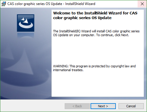
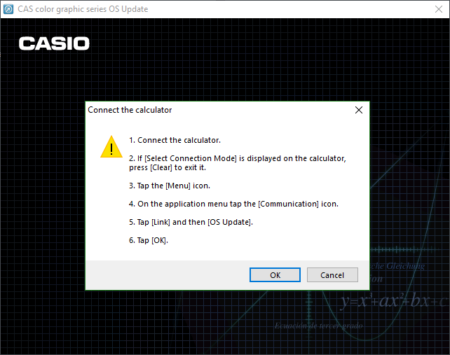
The weird behavior of the installer - giving no option for an install path, and immediately launching an application - made me suspicious that it wasn't actually installing anything. Instead, I believed the installer was instead simply acting as a way of containing and executing the firmware updater.
To determine if this was the case, I used the invaluable tool Process Explorer to view the subprocesses launched by the installer. Expecting to see a subprocess of the installer which was clearly the firmware updater, I was slightly surprised to see that the only subprocess was the Windows Installer process msiexec.exe.

As the msiexec.exe process was clearly the workhorse (or launching the workhorse), I opened Process Monitor and set a filter for msiexec.exe to catch when the true firmware updater was extracted or run. Before even proceeding through the installer, a flurry of events shot past in Process Monitor. Though most were typical actions taken by a Windows process, a long stream of FASTIO_WRITE events referencing an OSupdateDLL.dll appear within the garbage. Opening the directory containing the DLL revealed the true firmware update utility.

-
%TEMP\<random guid>\
- fxASPI.dll
- LanguageResource.dll
- OSupdateDLL.dll
Getting the firmware
With the actual firmware updater in hand, it was now time to extract the firmware which was pushed to the device. Sadly, the directory contained no firmware.bin or other obvious file, and as such the process became slightly harder. Almost immediately, however, the relatively large file size of OSupdateDLL.dll - almost 10 MB - caught my eye. Due to its size, I was sure the firmware was contained within the DLL.
With knowledge that large files can be stored inside PE files (EXEs, DLLs, etc.) in a section known as RCDATA, I opened the DLL in XN Resource Editor to see if any RCDATA sections were present within the DLL. Unsurprisingly, two sections (3069 and 3070) lay waiting. I extracted both for further investigation.
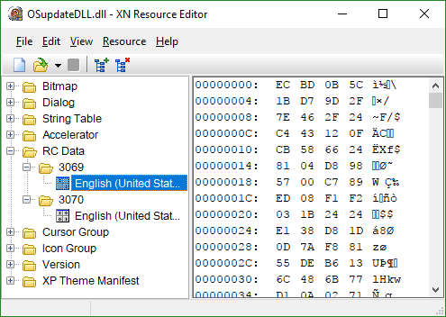
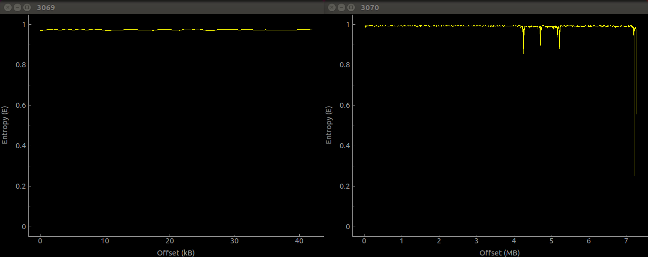
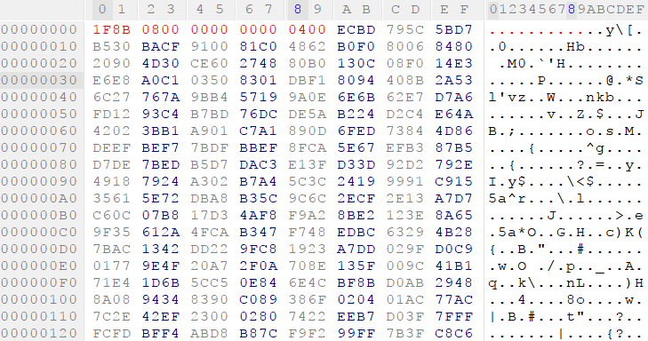
Viewing both sections in a hex editor revealed two similarities between the files. Both began with the two bytes 0xEC and 0xBD, and both appeared to be almost random data. Running the Unix strings utility over both revealed no human-readable data, and examining both with the binwalk tool showed no helpful information and very high entropy. Uh oh. There's obviously some encryption and/or compression going on here.
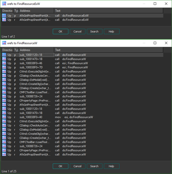
With hopes set on a simple or well-known compression algorithm undone by the firmware updater, I turned to disassembling the DLL file with IDA to find out how to get at the real firmware. Since the two binary blobs are located within the RCDATA of the DLL file, I started investigating by looking at the functions the DLL imports from the standard libraries which interact with PE resources. Since the function FindResource (and its Ex and W cousins) from KERNEL32 are used for this, it was my first port of call in the disassembly. Within the DLL, both the FindResourceW and FindResourceEx functions are imported, however the former is only used in a function called AfxGetPropSheetFont - not very likely to be the function we want. However, the FindResourceW function is used many times. This is probably the function we want to explore.
Since we're about to jump head-first into some assembly, it's important to quickly go over the calling convention used by applications on Windows. If you're already familiar, you can safely skip this next paragraph.
The calling convention of a platform is the method in which arguments are passed to functions and return values are passed back to the caller. On Windows, arguments to a function are passed through the stack, and pushed from right to left. That is, for a function f(a, b, c) the arguments are pushed in the order c, b, then a. Most functions return their value in the eax register, unless they return a more complicated data type such as a float or a double. If you're not an assembly expert, don't worry - I've tried to explain things as clearly as I can.
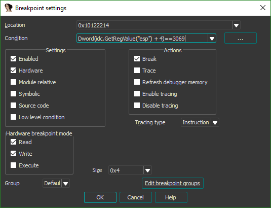
To determine exactly which call to the function was responsible for unpacking the firmware, I used a conditional breakpoint. Examining the arguments for the FindResourceW function showed that the index of the resource (3069 and 3070 our case) is passed into the function as the second argument of three (lpName). It'll therefore be the second value on the stack, after the value of lpType. To work out the offset we need to place on the stack pointer such that we can access the value of lpName, we must find out how many bytes an LPCTSTR is (the data type of lpType). Looking through the Windows documentation shows the data type is 4 bytes long (it's a pointer), and as such our pointer will be esp + 4.
We can then set our breakpoint on the FindResourceW function as shown. The following syntax is IDAPython, but the condition can also be written in IDC.

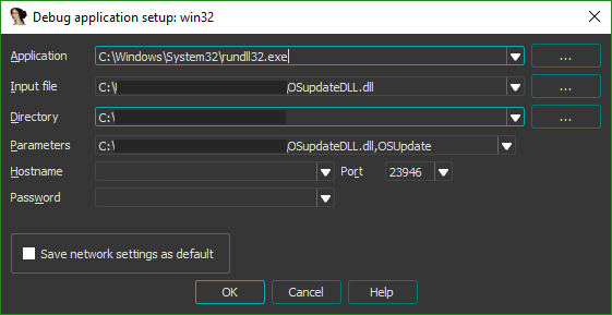
Though we're ready to run the application and observe where our breakpoint is hit, we've got to set up the debugger. Since the file we're disassembling is a DLL and not an EXE, it can't be executed directly and the debugger in IDA must be configured to invoke the DLL appropriately. This is where the Windows utility rundll32 comes in handy to launch the required function. Examining the exports of the OSupdateDLL.dll file shows two functions - DllEntryPoint and OSUpdate. We can assume that the latter is the true entry point to the DLL, and configure IDA to launch the DLL by invoking rundll32 with an argument specifying to call that function.
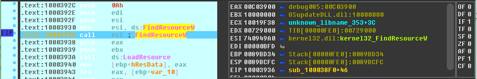
The breakpoint doesn't trigger straight away, but takes plugging in the calculator and running through the steps to begin the update for it to be hit. When it does, we're immediately shown the exact location within the code where our data is loaded.
Now begins the trickier part - deciphering the assembly to work out how the data is dealt with.
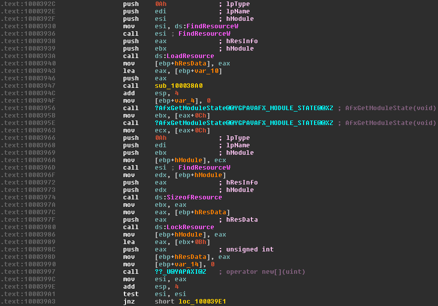
First, the function FindResourceW is called with the ID of our resource (in edi), which returns a handle to the resource. This handle is immediately pushed back onto the stack, becoming the hResInfo argument to LoadResource. This function returns a handle to the data associated with the resource which is then saved in [ebp+hResData] to be used later.
As we're looking for somewhere which uses the data contained within the resource, we're most interested in the call to the LockResource function. We can see that the value of [ebp+hResData] (the handle to the data, retrieved from the previous call to LoadResource) is moved into eax and then eax pushed onto the stack to serve as the first argument of LockResource. The function returns a pointer to the data, which is then saved in [ebp+hModule] (now repurposed to store the pointer). The size of the data is also retrieved through SizeOfResource, and stored in ebx.
IDA usefully notes the name of the next function we're interested in - operator new[](uint) - which is the constructor for a byte array. Here, some weird assembly tricks are used to calculate the size of the array we want to allocate. The size is calculated using the lea instruction which is typically used to Load Effective Address, i.e. load the address of a piece of data into a register. In this case, it's used to perform an addition and a move in one step, without effecting the contents of the original register. As square brackets in assembly are used to dereference a pointer (the * prefix operator in C), [ebx+0Bh] would typically dereference memory at the address ebx + 0Bh. However, since it's used as an argument to the lea instruction, the eax register is loaded with the address of [ebx+0Bh] which is simply ebx+0Bh. This usage is basically equivalent to mov eax, ebx+0Bh, since that instruction isn't possible.
With that in mind, we can see the array is created with a length which is 0x0B == 11 bytes longer than the actual size of the resource. The return value of the constructor (i.e. the pointer to the array, now stored in esi) is tested for a null pointer and then execution jumps to the point below.
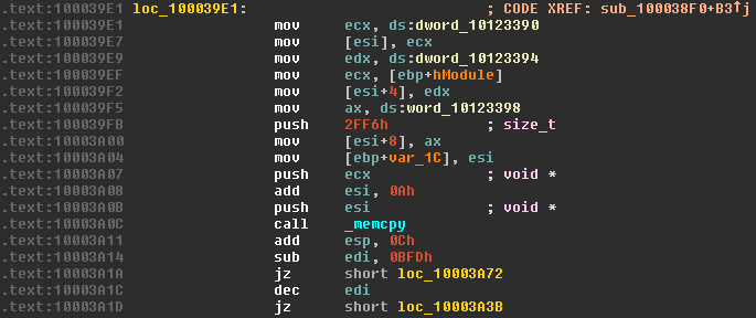
Here, quite a few memory operations act on the array we just created. First, the contents of the memory location dword_10123390 (helpfully named by IDA) are copied into the ecx register, then the contents of the ecx register copied into the first double word of the array. If you're more familiar with higher level languages, it may seem out of the ordinary to be copying a 4 byte data type into a byte array. But since we're dealing with the memory directly, it's bytes all the way down. Examining the contents of the memory location we copy from with IDA shows it contains the value 0x00088B1F. Naively, we'd assume the array would now look something like this:
| Index | 0 | 1 | 2 | 3 | ... |
|---|---|---|---|---|---|
| Data | 0x00 | 0x08 | 0x8B | 0x1F | ... |
But we've forgotten one important difference between processors - endianness. This is simply the order in which the bytes of a multi-byte number are stored in memory. On a little-endian machine, the number above would be stored in memory with the least significant byte first. The reverse is true on a big-endian machine, where the most significant byte is stored first. For example, if the number 0x12345678 was stored at a memory address x:
| Address | x+0 |
x+1 |
x+2 |
x+3 |
|---|---|---|---|---|
| Little-endian Data | 0x78 |
0x56 |
0x34 |
0x12 |
| Big-endian Data | 0x12 |
0x34 |
0x56 |
0x78 |
Since our machine is little-endian, after the copy, our array actually looks like this:
| Index | 0 | 1 | 2 | 3 | ... |
|---|---|---|---|---|---|
| Data | 0x1F | 0x8B | 0x08 | 0x00 | ... |
This process is repeated, copying the contents of dword_10123394 (value 0) into our array, starting at index 4. The contents of word_10123398 (value 0x0004) are then copied into our array starting at index 8, this time only writing two bytes due to the size of a word and the ax register (16 bits/2 bytes). Our array now looks like this:
| Index | 0 | 1 | 2 | 3 | 4 | 5 | 6 | 7 | 8 | 9 | ... |
|---|---|---|---|---|---|---|---|---|---|---|---|
| Data | 0x1F | 0x8B | 0x08 | 0x00 | 0x00 | 0x00 | 0x00 | 0x00 | 0x04 | 0x00 | ... |
We then call _memcpy to begin the bulk of our copying operation - moving part of the contents of the resource into our array. Initially, the value 0x2FF6 is pushed onto the stack to serve as the count argument to memcpy. The address pointing to the resource data, previously returned by LockResource and stored in [ebp+hModule], is moved into ecx and pushed onto the stack to serve as the source argument. The pointer to the array we allocated is also pushed to the stack, with the value 0xA added to it. This means the pointer no longer points to the first byte of the array, but the value at index 0xA - the first byte after the bytes we previously copied in. In C, this operation is as follows:
memcpy(array + 0xA, resourceData, 0x2FF6);
Our array now looks like this.
| Index | ... | 0x8 | 0x9 | 0xA - 0x2FFF | ... |
|---|---|---|---|---|---|
| Data | ... | 0x04 | 0x00 | <resource data 0x0 to 0x2FF5> | ... |
An interesting operation then occurs - the value 0xBFD is subtracted from edi (which stored the ID of the RCDATA resource we're currently operating on) and a conditional jump is performed. The operation jz checks the zero flag and jumps if it's reset (zero). In our case, the zero bit is set if the result of the subtraction is 0, i.e. edi - 0xBFD == 0 or, much more simply, edi == 0xBFD. If the jump isn't taken, the value of edi is decremented by 1, and a conditional jump on the zero flag is again performed. This is equivalent to jumping if edi - 0xBFD - 1 == 0 or edi == 0xBFE. These values - 0xBFD and 0xBFE are the values 3069 and 3070. Both jumps move code execution to two almost identical pieces of assembly.
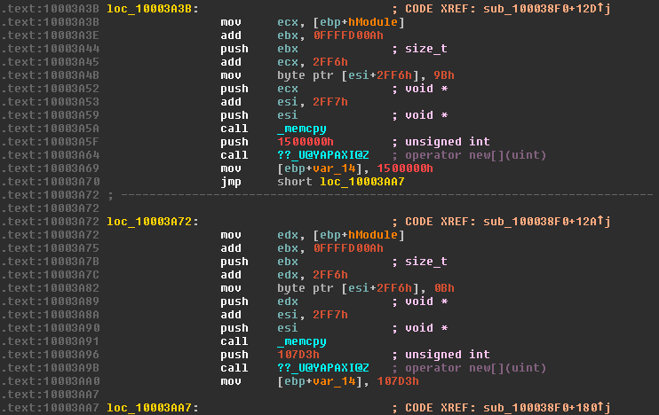
Since both sections of code appear functionally identical, it's much quicker to analyze just one section and use what we've learned in the first section to quickly decipher the second. Here we'll analyze the section loc_10003A3B, called when the resource ID is 3070. Two operations are interwoven here - a simple array access and a more complicated memcpy. The address of the array is moved into ecx, and the value 0xFFFFD00A added to the value of ebx, which still contains the size of the resource in bytes. This addition is actually relying on integer overflow to perform a subtraction. Since the register ebx is only 32-bit, when an addition occurs which sets a bit higher than can be represented in a 32-bit number, it's silently lost and the value wraps around. In this case, by adding 0xFFFFD00A to the length of our resource we effectively subtract 0x2FF6.
               max value: 0x0FFFFFFFF
0xFFFFD00A + 0x1500000 == 0x1014FD00A -> 0x014FD00A
0x1500000 - 0x2FF6                    == 0x014FD00A
This newly calculated value is then pushed onto the stack, and IDA helpfully tells us this becomes the count argument of memcpy (by showing us the type is size_t). 0x2FF6 is added to ecx, the address of our resource data, and pushed to the stack to become the source. Before the destination argument is pushed onto the stack, a single byte of the array is set. The byte 0x9B is copied to [esi+2FF6h]. Since in the previous memcpy operation, 0xA is added to esi to point at the first byte after our header, the byte is actually copied to the index 0x2FF6 + 0x0A, or index 0x3000. The value 0x2FF7 is added to esi leaving it pointing to the index 0x3001 of the array, and pushed to the stack to become the destination. The two operations are equivalent to the following C code.
array[0x3000] = 0x9B;
memcpy(array + 0xA + 0x2FF6, resourceData + 0x2FF6, resourceLength - 0x2FF6);
If we spend a moment to work out exactly what these operations are intended to achieve, a much clearer picture emerges. First, we copy a 10 byte header to our array. Then, we copy 0x2FF6 bytes from the beginning of our resource to the array at the index just after the header. Then, the byte at index 0x3000 is set to a hard-coded value, and a copy of <resource length> - 0x2FF6 bytes to the position 0x3001 in the array is performed. We've reconstructed a file whose header and a specific byte in the middle of the file has been removed. Our array now looks something like this:
| Index | ... | 0x8 | 0x9 | 0xA - 0x2FFF | 0x3000 | 0x3001 - end |
|---|---|---|---|---|---|---|
| Data | ... | 0x04 | 0x00 | <resource data 0x0 to 0x2FF5> | <missing byte> | <resource data 0x2FF6 to end> |
This process is the same for the other RCDATA resource, with the only difference being the value of the byte which is written at position 0x3000.
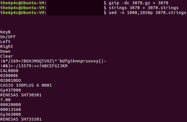
It's now time to work out exactly what's done with the data in this buffer. The hard-coded header that's added to both files serves us well, and searching for 1F 8B 08 on Google immediately reveals the data is a GZIP file. Now it's time to reconstruct our file and extract it, hopefully revealing a raw firmware image. We'll open the 3070 file in our favorite hex editor, and add the header and missing byte at 0x3000 (after the header's added). I'll only do this for the main firmware in 3070, but the process is exactly the same for the firmware in 3069.
We'll save this new file as 3070.gz so the gzip command utility recognizes it, extract it, and presto!
Soon enough, I'll write a Part 2 exploring the firmware image itself and the interesting SuperH architecture it runs upon. Thanks for reading this far. If there's anything I can improve on in my writing, I'd love to hear it, send your constructive criticism my way!